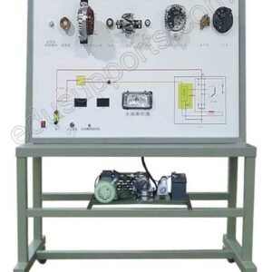
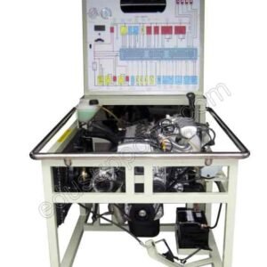
Сайт Интегрированный гидравлический и пневматический тренажер is a versatile “two-in-one” system, featuring hydraulic training on one side and pneumatic training on the other, each with an independent PLC controller. This Интегрированный гидравлический и пневматический тренажер allows users to conduct basic experiments in both pneumatic and hydraulic control circuits. It also supports advanced training modules, such as electric-pneumatic control, pneumatic-hydraulic control, electric-hydraulic control, and comprehensive pneumatic-electric-hydraulic control. Ideal for skill development in PLC, solenoids, pneumatics, hydraulics, and relays, this Интегрированный гидравлический и пневматический тренажер is an excellent tool for vocational training and education.
- Компоненты промышленного класса:The trainer uses real hydraulic and pneumatic components, execution modules, relay control units, and PLCs, ensuring practical, industry-relevant training.
- Modular Design:Hydraulic and pneumatic modules with elastic pins can be easily assembled on the aluminum T-slot training panel, enabling the creation of various circuits.
- Advanced PLC Integration:Equipped with a Mitsubishi PLC FX1N-20MR, featuring a 12-point signal input and an 8-point signal output, providing robust control capabilities.
- High-Pressure System:The system supports a rated pressure of up to 6.3Mpa, making it suitable for students, scholars, and professionals in hydraulic engineering to design and experiment with complex hydraulic transmission and programmable control systems.
- Особенности безопасности:The trainer includes three-phase power leakage protection and DC power supply with overcurrent protection, ensuring a safe learning environment.
Typical Hydraulic Training Contents
- Схемы направленного управления
- 1 Sequence Action Circuit
- 1.1 Reversing Circuit using Manual Directional/Reversing Valve
- 1.2 Reversing Circuit via Pilot Oriented Pressure Relief/Overflow Valve
- 2 Sequence Action Circuit
- 2.1 Sequence Action Circuit with Sequence Valve
- 2.2 Sequence Action Circuit using Pressure Relay
- 2.3 Sequence Action Circuit with Limit Switch
- 2.4 Sequence Action Circuit using Travel/Reversing Valve
- 3 Lock Circuits
- 3.1 Lock Circuit using Mid-Position Function Solenoid Reversing Valve
- 3.2 Lock Circuit with Pilot Check Valve
- Схемы управления давлением
- 1 Pressure Regulating Circuit
- 1.1 Single-Stage Pressure Regulating Circuit
- 1.2 Two-Stage Pressure Regulating Circuit
- 2 Pressure Reducing Circuit
- 2.1 Pressure Reducing Circuit using Pressure Reducing Valve
- 3 Booster Circuit
- 3.1 Booster Circuit using Booster Cylinder
- 4 Pressure Relief (Pressure-Venting) Circuit
- 4.1 Pressure Relief Circuit via Reversing Valve
- Схемы управления скоростью
- 1 Throttle Speed Regulating Circuit
- 1.1 Oil-Inlet Throttle Speed Regulating Circuit
- 1.2 Oil-Return Throttle Speed Regulating Circuit
- 1.3 Reversing Speed Regulating Circuit with Gear Pump
- 1.4 Complex Speed Control Circuit using Joint Gear Pump and Speed Regulating Valve
- 1.5 Secondary Feed Circuit using Series Speed Regulating Valve
- 1.6 Secondary Feed Circuit using Parallel Speed Regulating Valve
- 2 Speed Shift Circuit
- 2.1 Speed Shift Circuit using Flow Valve
- 3 Synchronization Circuit
- 3.1 Synchronization Circuit with Series Hydraulic Cylinders
Typical Pneumatic Training Contents
- Схемы управления давлением
- 1 Secondary Pressure Control Circuit
- 2 High and Low Pressure Shift Circuit
- 3 Overload Protection Circuit
- 4 Unloading Circuit
- Схемы направленного управления
- 1 Single-Acting Cylinder Reversing Circuit
- 2 Double-Acting Cylinder Reversing Circuit
- 3 Single-Cylinder Reciprocating Control Circuit
- 4 Single-Cylinder Continuous Reciprocating Control Circuit
- 5 Sequence Action Circuit for Straight Cylinder and Rotating Cylinder
- 6 Multi-Cylinder Sequence Action Circuit
- 7 Double Cylinders Synchronous Action Circuit
- Схемы управления скоростью
- 1 Single-Acting Cylinder Speed Regulating Circuit
- 2 One-Way Speed Regulated Circuit for Double-Acting Cylinder
- 3 Two-Way Speed Regulated Circuit for Double Pneumatic Acting Cylinder
- 4 Speed Shift Circuit
- 5 Buffer Circuit
- Другие схемы
- 1 Relay Circuit
- 2 Counting Circuit
- 3 Interlock Circuit
- 4 Four Cylinders Linkage Circuit
- 5 Application Circuit of OR-Gate Type Shuttle Valve
- 6 Application Circuit of Quick Exhaust Valve
- Двигатель
- Power: 750W
- Rated Voltage: 380V
- Шиберный насос
- Maximum Pressure: 7MPa
- Displacement: 8mL/r
- Rotational Speed: 1400 r/min
- Hydraulic Pump Station
- Maximum Volume: 90L
- Noise Level: ≤58dB
- Air Compressor
- Power: 250W
- Power Supply: 220V
- Rated Output Pressure: 1MPa
- Noise Level: ≤58dB
- Источник питания
- AC Supply: Three-Phase Five-Wire, 380V ± 10%, 50Hz


