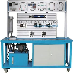
The Ultimate Hydraulic Controlled Excavator Training System is a specialized platform designed for professional hydraulic circuit design and demonstration. This advanced training tool enables students to study the internal structure and working principles of various hydraulic components in detail. Each transparent hydraulic component is crafted to reflect the actual internal structure of industrial hydraulic systems, allowing for an accurate representation of how these components function in real-world applications.
Made from high-quality imported transparent plexiglass, the components offer superior visibility, compactness, and lightweight design, making them ideal for educational use. Students can explore the structure, working principles, and functions of individual hydraulic components, as well as construct fundamental hydraulic circuits to observe spool movement and fluid flow within the system.
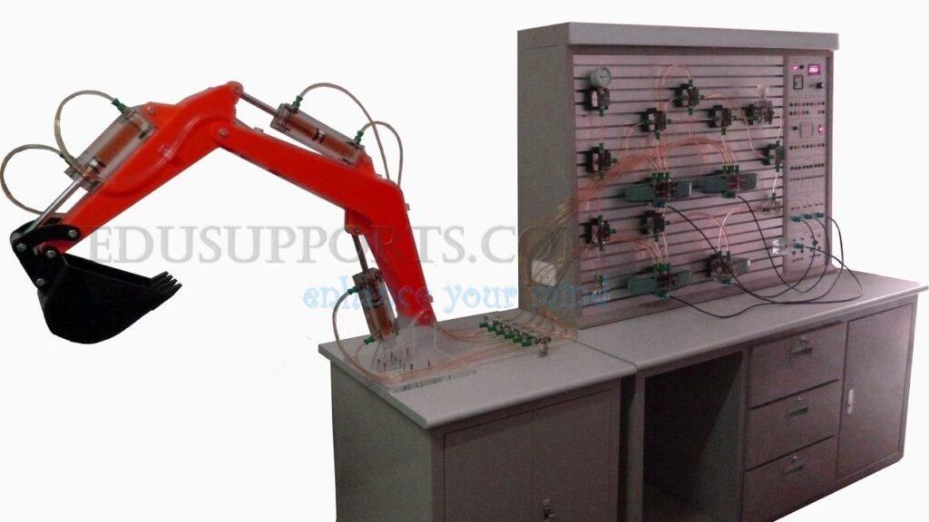
The Ultimate Hydraulic Controlled Excavator Training System is designed to replicate the actions of an excavator, including mining, discharging, and lifting, controlled via the training bench. This hands-on experience allows students to gain a comprehensive understanding of the hydraulic systems and control principles behind excavator operations.
The Ultimate Hydraulic Controlled Excavator Training System is an essential tool for teaching various hydraulic disciplines, providing practical insights into the complexities of hydraulic systems.
- T-Slot Design for Easy Operation:The training panel features a T-slot design, allowing all hydraulic components to be inserted easily using rapid joints for seamless operation.
- Transparent Plexiglass Components:The hydraulic components are crafted from transparent plexiglass, vividly demonstrating the structure and working process of each element.
- Leak-Proof Circuit Assembly:Circuit experiments utilize a leak-proof, fast-insert interface, ensuring that experiment setups are simple, quick, and clean.
- Quick-Slab Fixed Components:All hydraulic components are securely fastened using quick-type slab fixings for stability during experiments.
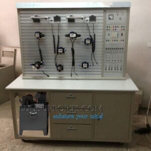
- Dual Control Methods:The system supports two control methods—PLC control and relay control. Using a programmable logic controller (PLC) optimizes control plans, allowing trainees to compare and understand the advantages of advanced PLC control.
- Mitsubishi PLC Integration:The PLC utilizes the Mitsubishi FX1S-20MR model with 12 inputs and 8 relay outputs. Integrating PLC with the hydraulic system facilitates automatic hydraulic control experiment teaching.
1.Directional Control Circuits
Sequence Action Circuits
1.1.1 Reversing circuit using a manual directional/reversing valve.
1.1.2 Reversing circuit controlled by a pilot-oriented pressure relief valve/overflow valve.
Lock Circuits
1.3.1 Lock circuit featuring a mid-position function solenoid reversing valve.
1.3.2 Lock circuit using a pilot check valve.
2.Pressure Control Circuits
Pressure Regulating Circuits
2.1.1 Standard pressure regulating circuit.
2.1.2 Two-stage pressure regulated circuit.
Booster Circuits
2.3.1 Booster circuit using a booster cylinder.
Pressure Relief Circuits
2.4.1 Pressure relief circuit utilizing a reversing valve.
3.Speed Control Circuits
Throttle Speed Regulating Circuits
3.1.1 Oil-inlet throttle speed regulating circuit.
3.1.2 Oil-return/back throttle speed regulating circuit.
Speed Shift Circuits
3.2.1 Speed shift circuit using a flow valve.
Synchronization Circuits
3.3.1 Synchronization circuit involving series hydraulic cylinders.
4.Excavator Training Contents
Excavator Hydraulic Circuits
4.1.1 Demonstration of mining, discharging, lifting, and other actions using a physical excavator.
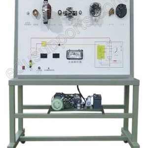
4.1.2 Understanding hydraulic system components, working principles, and internal structure.
4.1.3 Disassembly and assembly of an excavator’s hydraulic system.
4.1.4 Electrical control system circuit experiments for excavators.
4.1.5 Measurement of parameters such as pressure and flow in the excavator hydraulic system during experiments.
1.Motor
Power: 400W
Speed Range: 0-1500 r/min
2.Hydraulic Pump
Maximum Pump Pressure: 2.5 MPa
Circuit Action Pressure: 0.3-0.8 MPa
Noise Level: ≤58 dB
Dimensions: 550mm × 350mm × 600mm
3.Power Supply
AC Supply: AC 220V, 50Hz
DC Supply: Input AC 220V, Output DC 24V/3A
4.Bench Dimensions
Bench Size: 1250mm × 650mm × 1800mm
Overall Dimensions During Excavator Operation: 1850mm × 650mm × 1850mm