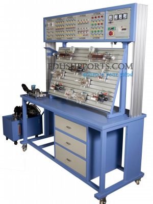
The Transparent Hydraulic Trainer is a specialized platform for designing and demonstrating hydraulic circuits, making it ideal for hydraulic teaching and training. This Transparent Hydraulic Trainer allows students to easily study the internal structure and working principles of various hydraulic components. Each transparent hydraulic component is crafted to mirror the actual internal structure of industrial-grade components, providing an accurate reflection of the underlying principles.

- T-Slot Training Panel:The training panel is designed with T-slots, and all hydraulic components use rapid joints, ensuring easy and efficient operation.
- High-Quality Transparent Components:Made from imported plexiglass, these components offer high transparency, compact size, and lightweight design, vividly showcasing the structure and operational process of hydraulic systems.
- Leak-Proof Circuit Assembly:The circuit experiment uses a leak-proof, quick-insert interface, simplifying the assembly process and keeping it clean.
- Quick-Type Slab Fixing:All hydraulic components are securely fixed using a quick-type slab, ensuring stability during training.
- Dual Control Methods:The system supports two control methods—PLC control and relay control. The integration of PLC (Programmable Logic Controller) allows for an optimized control plan, providing trainees with a clear understanding of the advantages of PLC control.
- Automatic Hydraulic Control:Combining PLC and hydraulic systems, the trainer enables comprehensive automatic hydraulic control experiments, enhancing the learning experience for students across various hydraulic disciplines.
1. Directional Control Circuits
1.1 Reversing Action Circuits
1.1.1 Reversing Circuit of Reversing Valve
1.2 Lock Circuits
1.2.1 Lock Circuit of Reversing Valve (O-Type Function)
1.2.2 Lock Circuit by Pilot Check Valve
1.3 Sequence Action Circuits
1.3.1 Sequence Action Circuit of Sequence Valve
1.3.2 Sequence Action Circuit of Pressure Relay
1.3.3 Sequence Action Circuit of Position Switch
1.3.4 Sequence Action Circuit of Stroke Valve
1.3.5 Sequence Action Circuit of PLC-Controlled Position Switch
1.3.6 Sequence Action Circuit of PLC-Controlled Pressure Relay
2. Pressure Control Circuits
2.1 Pressure Regulated Circuits
2.1.1 Pressure Regulating/Setting Circuit
2.1.2 Two-Stage Pressure Regulated Circuit
2.2 Pressure Reducing Circuits
2.2.1 Pressure Reducing Circuit of Pressure Reducing Valve
2.3 Booster Circuits
2.3.1 Booster Circuit of Booster Cylinder
2.4 Pressure Relief Circuits (Pressure-Venting)
2.4.1 Pressure Relief Circuit by Reversing Valve
3. Speed Control Circuits
3.1 Throttle Speed Regulating Circuits
3.1.1 Oil-Inlet Throttle Speed Regulating Circuit
3.1.2 Oil-Inlet Throttle Speed Regulating Circuit
3.1.3 Speed Regulating Circuit of Variable Pump
3.1.4 Complex Speed Regulating Circuit by Joint Variable Pump and Speed Regulating Valve
3.1.5 Secondary Feed Circuit
3.2 Speed Shift Circuits
3.2.1 Speed Shift Circuit of Flow Valve Short-Contact
1.Motor
- Rated Voltage: DC 220V
- Power: 300W
- Fuel Tank: Nominal Capacity 30L
2.Power Supply
- AC 220V, 50Hz
- DC 24V/3A
3.Bench Dimensions
- L × W × H = 1560 × 650 × 1800 mm


