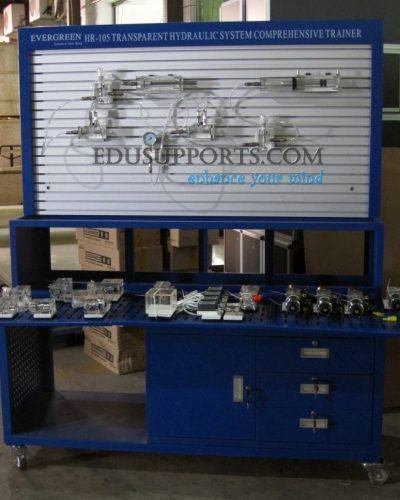
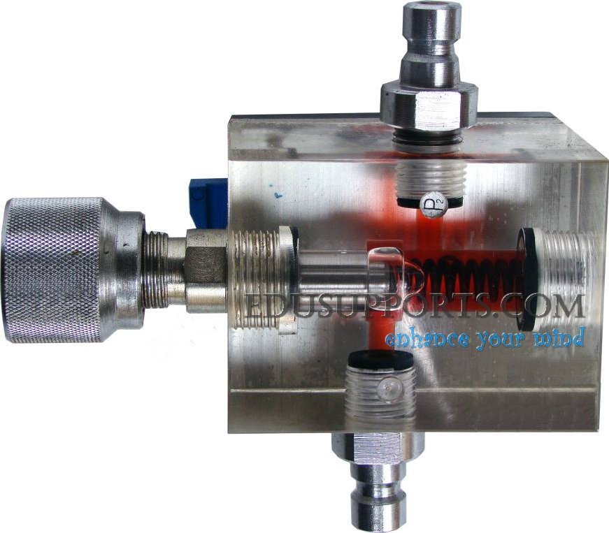
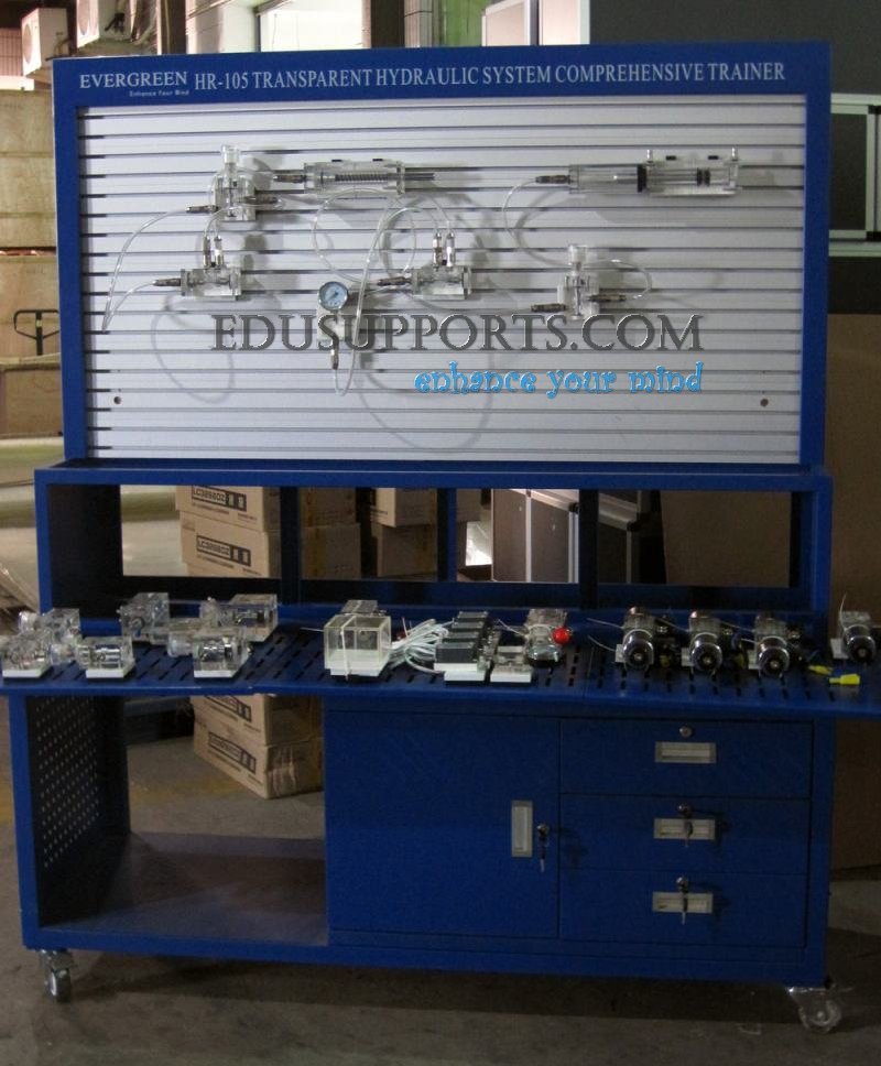
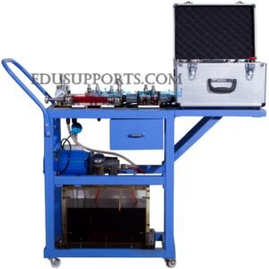
Transparent Hydraulic Comprehensive Trainer is a specialized platform designed for hydraulic circuit design and demonstration, ideal for use in hydraulic teaching environments. It allows students to easily study the internal structure and working principles of various hydraulic components. All components are crafted to accurately reflect the internal structure and functioning of industrial hydraulic parts.
Constructed from high-quality, imported transparent plexiglass, the Transparent Hydraulic Comprehensive Trainer offers excellent clarity, compact size, and lightweight features. Students can observe and understand the structure, operation, and function of individual hydraulic components. They can also assemble basic hydraulic circuits to study the movement of spools in the loop tank and the fluid flow direction within the spool body.
This Transparent Hydraulic Comprehensive Trainer supports teaching and training across multiple hydraulic disciplines, including:
- Understanding the composition of hydraulic transmission systems.
- Observing, disassembling, and assembling various parts of a hydraulic transmission system.
- Conducting PLC electrical control experiments for machine-electric-hydraulic integrated control.
- Constructing basic hydraulic circuits for practical learning.

Versatile Circuit Design: Capable of supporting up to 90 different circuit experiments, offering extensive training possibilities.
Three Control Modes: The system supports three control modes: PLC control, relay control, and manual control.
- Two automatic control modes: PLC and relay control.
- Solenoid valve control with three methods: a. Pressure relay control (2 inputs) b. Proximity switch control (4 inputs) c. Manual control (6 inputs)
T-Slot Training Panel: The training panel features a T-slot design, with hydraulic components using rapid joints for easy insertion and operation.
Transparent Plexiglass Components: The hydraulic components are crafted from transparent plexiglass, vividly demonstrating their structure and working process.
Leak-Proof Fast Connectors: Circuit experiments utilize leak-proof, quick-connect interfaces, making assembly of experimental circuits simple, fast, and clean.
Quick-Fix Mounting: All hydraulic components are mounted using a quick-type slab fixed floor, ensuring stability and ease of setup.
High-Precision Components: The hydraulic components are manufactured with high precision, adhering to standard physical structures. The gap between the valve body and valve spool is between 0.015-0.028mm, with an accuracy of ±0.2 mm.
Excellent Sealing Performance: The system offers outstanding sealing performance, with no leakage of hydraulic components when operating under pressures up to 0.8 MPa.
Part A: Basic Hydraulic Circuit Design and Training
1.Pressure Control Circuits
- Pressure Regulation Circuits
- Single-stage pressure regulation using a pressure relief valve/overflow valve.
- Multi-stage pressure regulation with multiple pressure relief valves.
- Pressure Reduction Circuits
- Single-stage pressure reduction.
- Pressure Holding Circuits
- Pressure retention using a pilot check valve.
- Decompression Circuits
- Decompression using a throttle valve.
- Decompression with a sequence valve.
- Pressure Relief Circuits
- Pressure relief using a two-position, two-way valve.
- Pressure relief with a pilot-oriented pressure relief valve.

2.Speed Control Circuits
Speed Regulation Circuits
- Oil-inlet throttle speed regulation (constant pressure).
- Oil-return throttle speed regulation (constant pressure).
- By-pass throttle speed regulation (variable pressure).
- Fast-speed movement via differential connection.
- Speed regulation using a speed control valve.
- Speed reduction/slow-speed control with a solenoid valve.
- Differential circuit with a two-position, three-way valve.
- Secondary feed circuit.
3.Directional Control Circuits
Reversing Circuits
- Reversing action using a reversing valve.
5.Relay Control Circuits
- Sequence control using relays and proximity switches.
4.Twin Cylinder Synchronization and Sequence Circuits
- Sequence Action Circuits
- Sequence control with a sequence valve.
- Sequence action with a proximity switch and reversing valve.
- Sequence action using a pressure relay and proximity switch.
- Synchronization Circuits
- Twin cylinder synchronization.
- Synchronization using a shunt valve.
- Synchronization with a speed regulating valve.
- Synchronization via a throttle valve.
- Lock Circuits
- Locking mechanism with a reversing valve.
- Locking using a pilot check valve.
- Locking with a one-way valve.
Part B: PLC Electrical Control Experiments (Machine-Electric-Hydraulic Integration)
- PLC Programming Instructions and Ladder Programming
- Learn PLC programming and create ladder logic diagrams.
- PLC Software Utilization
- Use and master PLC programming software.
- PLC and Computer Communication
- Facilitate communication between PLC systems and computers.
- PLC Applications in Hydraulic Systems
- Explore and optimize PLC applications within hydraulic transmission systems.
Part C: Hydraulic Circuit Design Simulation (Optional)
- Speed shift circuits using throttle valves.
- Synchronization circuits with throttle valves.
- Oil-inlet throttle speed regulation.
- Two-stage pressure regulation circuits.
- By-pass throttle speed regulation.
- Three-position, four-way reversing valve circuits.
- Sequence action circuits with sequence valves.
- Sequence action circuits using pressure relays.
- Sequence action circuits via proximity switches.
- Pressure regulation by adjusting spring pressure in relief valves.
- Differential circuits.
- Two-position, four-way reversing circuits.
- Decompression circuits controlled by solenoid valves.
- Pressure holding circuits for isolating pressure fluctuations.
- Oil-return throttle speed regulation.
- Synchronization circuits via throttle valves.
- Fast and slow speed shift circuits.
- Balancing circuits.
- Lock circuits using pilot check valves.
- Pressure holding circuits with pilot check valves.
1.Motor
- Rated Power: 0.75 KW
- Rated Speed: 1420 RPM
- Power Supply: AC 380V
2.Quantitative Gear Pump
- Rated Displacement: 7.8 cc/rev
- Rated Pressure: 0.3-2 MPa (adjustable)
3.PLC Controller
- Model: Mitsubishi FX1S-20MR (customizable to other brands/models as per requirements)
4.Dimensions
- Size: 1600×660×1800 mm (LWH)
5.Electric Operation and Control Circuit
- PLC Host Module: Mitsubishi FX1S-20MR with 20 I/O ports (12 DC inputs, 8 relay outputs).
- Control Button Module: Includes 6 self-resetting DPDT green button switches and 6 self-locking DPDT red button switches.
- Intermediate Relay Module: Equipped with 4 DC 24V relays, featuring input/output terminals on the panel with corresponding LED indicators.
- Time Relay Module: Features 2 DC 24V time relays with input/output terminals on the panel.
- Electronic Control Module: Includes 6 solenoid valve interfaces, 2 pressure relay interfaces, and 4 stroke switch interfaces.
- Main Control Module: Equipped with 3 AC 450V voltmeters for three-phase output voltage indication, 1 DC 30V voltmeter for switching power supply voltage, and motor start/stop control buttons.


