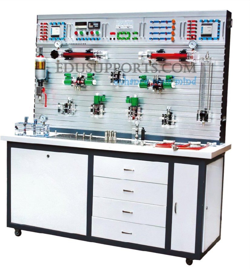
This Cutting-Edge Visible Hydraulic Drive and Controlled Trainer serves as a professional platform for hydraulic circuit design and demonstration. It allows for an in-depth study of the internal structure and working principles of various hydraulic components in educational settings. Each transparent hydraulic component is crafted to mirror the actual internal structure of industrial hydraulic parts, providing a clear understanding of their tectonic and operational principles. The components, made from transparent plexiglass, offer high clarity, compact size, and lightweight benefits. Students can explore the structure, working principles, and functions of individual hydraulic components and create fundamental hydraulic circuits to observe spool movement and fluid flow within the system. This Cutting-Edge Visible Hydraulic Drive and Controlled Trainer supports a wide range of hydraulic teaching and training activities, including:
- Understanding the composition of hydraulic transmission systems.
- Studying the structure and working principles of hydraulic transmission system parts, including observation, disassembly, and assembly training.
- Conducting PLC electrical control experiments, integrating machine-electric-hydraulic controls.
- Constructing basic hydraulic circuits.

- T-Slot Training Panel:The panel features a T-slot design, enabling easy and rapid insertion of hydraulic components with quick-connect joints for streamlined operation.
- Transparent Hydraulic Components:Made from high-quality plexiglass, the hydraulic components provide a clear view of their structure and operation, vividly demonstrating their working processes.
- Leak-Proof Circuit Assembly:Circuit experiments are simplified with leak-proof, fast-connect interfaces, making assembly quick, clean, and efficient.
- Quick-Slab Fixed Components:All hydraulic components are securely mounted on a quick-type slab, ensuring stable and reliable performance.
- High-Precision Manufacturing:Hydraulic components are crafted with high precision, adhering strictly to standard physical structures for accuracy.
- Superior Sealing Performance:The system ensures excellent sealing, with no leakage when operating under pressures up to 0.8 MPa.
- Versatile Control Modes:The system supports three control modes: PLC control, relay control, and manual control, offering flexibility in operation.
Part A: Basic Hydraulic Circuit Design and Training
1.Pressure Control Circuits
Pressure Regulated Circuit:
- Regulation via pressure relief/overflow valve
- Multi-stage regulation with multiple pressure relief/overflow valves
Pressure Reducing Circuit:
- Single-stage pressure reduction
Pressure Holding Circuit:
- Holding pressure using a pilot check valve
Decompression Circuit:
- Decompression using a throttle valve
- Decompression with a sequence valve
Pressure Relief (Pressure-Venting) Circuit:
- Relief via two-position, two-way valve
- Relief using a pilot-oriented pressure relief/overflow valve
- Relief through a two-position, two-way valve
2.Speed Control Circuits
Speed Regulated Circuit:
- Oil-inlet throttle regulation (constant pressure throttle governor)
- Oil-return throttle regulation (constant pressure throttle governor)
- By-pass throttle regulation (variable pressure throttle governor)
- Differential connection for fast-speed movement
- Speed regulation using a speed regulating valve
- Slow-speed circuit with solenoid and speed regulating valves
- Differential circuit with two-position, three-way valve
- Secondary feed circuit
3.Directional Control Circuits
Reversing Circuit:
- Reversing using a reversing valve
4.Double/Twin Cylinders Synchronous/Sequence Circuit
Sequence Action Circuit:
- Sequence control via sequence valve
- Sequence action with proximity switch and reversing valve
- Sequence action using pressure relay and proximity switch
Synchronization Circuit:
- Double/twin cylinder synchronization
- Synchronization with shunt valve
- Synchronization using speed regulating valve
- Synchronization via throttle valve
Lock Circuit:
- Locking with reversing valve
- Locking using pilot check valve
- Locking with one-way valve
4.Relay Control Circuits
- Sequence control using relays and proximity switches
Part B: PLC Electrical Control Experiments (Machine-Electric-Hydraulic Integrated Controlled)
- PLC programming instructions and ladder programming
- Learning and using PLC programming software
- PLC-computer communication
- PLC applications and optimization in hydraulic transmission systems
1.Three-Phase Motor
- Rated Power: 2.2 kW
- Rated Speed: 1420 r/min
2.Quantitative Vane Pump
Rated Displacement: 10 ml/rev
3.Operating Pressure: 0.8 MPa
4.Operating Voltage: 380V
5.Dimensions: 1500mm × 650mm × 1700mm